Intraoral 3D Scanner » Introduction
Development of an Intraoral Scanning System for dentistry was the main topic of my doctoral degree, dissertation title is "Analysis of 3D Shape Measurement for Fringe Projection Profilometry based Intraoral Scanner". The starting date of the project was 2009 but I took control on this project in 2010. The total duration of the project was 5 years.
Intraoral 3D Scanner » Concept of the System

Intraoral 3D Scanner » Design of the 1st Device
This scanning device was the first hardware of the IOS project, and developed in 2010. It comprises a laser diode (LD) beam, a micro charge-coupled device (CCD) for capturing the dental images, a grating for producing the series of parallel fringe strips, a PZT for phase shifting the interferogram, a set of optical lenses, and a Polhemus device sensor. Note that instead of computer generated phase-shifting fringe strips, the fringe strips are produced by the grating and PZT graticule. The structured light of the fringe pattern of the laser beam is projected onto the shape of the tooth. The CCD imaging device captures the projected patterns which are modulated by the tooth profile and then transmitted to the host computer for image processing, reconstruction of the depth of the tooth shape, display, and so forth.

|

|
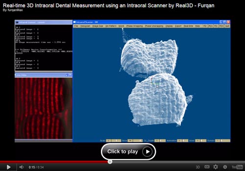
Intraoral 3D Scanner » 1st Device Videos

|
|
Intraoral 3D Scanner » Design of the 2nd Device
Based on the observation from the 1st IOS device, the 2nd version of the IOS device was developed with completely a new idea in term of hardware. In the second device, most of the issues were resolved. However, there were still some issues in the second device which will be fixed in the 3rd device.
In this version, several optical lenses were utilized which were designed for light coupling and filtering. A collimating automatic double lens was used for straightening the fringe strips produced by the grating after the high illuminated LD beam passes through the graticule and a set of optical lenses. Three 90 degree optical reflector mirrors were used for guiding light onto the surface, and five 90 degree reflector mirrors were utilized to guide the reflected light patterns to the CMOS image sensor. The CMOS image sensor with an image resolution of 640×480 and the pixel size was 4 µm is used. A Voice Coil Actuator was utilized in order to move graticule in a manner of to-and-fro motion and its CAD design can be seen in the fig. Some advantages of voice coil actuators are small in size, direct drive, high force to weight ratio, high acceleration, no cogging and commutation, and smooth motion, etc. In this version, the probe length was further minimized to
keep the scanner body as compact as possible for the convenience of dentists and their clients. The probe which has to be inserted into the mouth has a section of about 19.50 × 23 mm and a length of 83.01 mm. The housing was fabricated with aluminum material in order to make it light weight.

|
Intraoral 3D Scanner » Design of the 3rd Device
The third version of the IOS device was designed in 2013 with some more improvements such as hardware temperature control, visible high power LED as a new light source, and angle between the sensor and laser ray. The LED was a HL6501MG 0.65 μm band AlGaInP laser diode with a multi-quantum well (MQW) structure. The CAD and optical design of the 3rd IOS device can be illustrated in the following figure. In this version, the probe height was little increased from 20 mm to 23 mm due to increasing the angle between sensor and laser ray from 5 degree to 10 degree. The probe which has to be inserted into the mouth became about 19.50 × 23 mm and a length of 83.01 mm.

|

|
Intraoral 3D Scanner » 3rd Device Videos

|
Intraoral 3D Scanner » Articulated Robot Arm
To develop such a system was just an Idea.
When a dentist conducts 3D measurement by holding the intraoral scanner, the hand shaking could create unexpected results, and it could also be harmful for the dental patient. Therefore, it is needed to develop an automatic system that should perform the scanning operation automatically. In order to scan a complete tooth profiles including occlusal, lip, and tongue, minimum two scans will be required from two different orientations as shown in the figure which describes the schematic diagram for articulated robot arm to perform intraoral scanning in the mouth cavity. Therefore, multiple scans should be performed from different views and all scans must be registered together in a common coordinate system. On the basis of above assumptions, an articulated robot arm is developed which was very similar to a 3-links robot arm.

|