Real3d Scanner V2 » CNC Machining Center Simulator
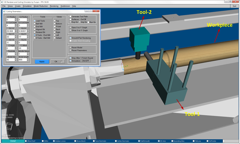
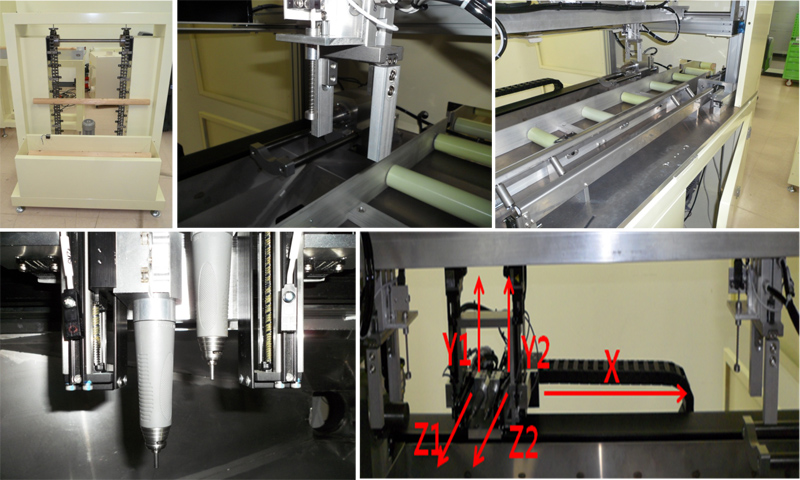
A 3D wood cutting simulation system is developed which is highly similar to the real-world wood cutting machining center. Both vertical and horizontal machining can be implemented on the cylindrical model by changing various parameters that relate to the cutting. Because manufacturers use different kinds of cutter shapes to cut the wood material according to different requirements; therefore, various cutting tools with different shapes are rendered in this system. All tools are surface-based modeled with excellent visual quality.
How can I use CNC Cutting Simulation module?
Left Section
The left section of the window shows the CNC cutting conditions for wood processing. It includes cutters radius, depth of cut, feed rate of the cutter, spindle speed, length of the work piece, diameter of the work piece, cutter angle (if necessary), offset between both cutters, and locations of cutters. We can set any cutting conditions according to our requirement at real-time.
Tools Section
Various tools can be used for processing from this section such as End Mill, Ball Mill, Horizontal Aligned bit, and Horizontal Rotatable bit. Three-dimensional material removal operation can also be performed using both tools, simultaneously.
Views Section
We can visualize the cutting simulation from various views such as top, bottom, left, right, front, and back.
Right Section - Tool Path Generation
Once the offset surfaces are generated, then if it is checked, it means tools will follow the surface profile of the model. We can export the generated G-code after completion of one round, and if it is unchecked it means normal cutting simulation mode is ON.
Surfaces – On/Off
If it is checked offset surfaces will be ON, otherwise OFF.
Exp GC (Export G-code)
Generated G-code can be exported by clicking on this button.
Imp GC (Import G-code)
In order to run generated G-code, it can be imported by clicking on this button.
Run Gc (Run G-code)
After import the G-code file, If it is checked then G-code running mode will be On, then simulation can be On or Off from “Simulation – On/Off check button”.
Save X-vs-Y Graph
After cutting simulation, we can save the surface profile data in 2D XY plane.
Show X-vs-Y Graph
After cutting simulation, we can visualize the surface profile of the work piece in 2D XY plane.
Smooth/Flat Rendering
In order to visualize smooth cutting surface, smooth mode can be activated.
Reset Model
Reset model to its original state.
Reset Parameters
Reset cutting parameters.
Stop After 1 Finish Round
If it is checked the simulation will be stopped after 1 finish round.
Simulation – On/Off
If it is checked the Simulation will be turned ON, otherwise OFF.

