Real3d Scanner V2 » Real-time Structured Light 3D Scanning
Using Realtime 3D Scanning module, we can perform realtime 3D scanning on any object. We just need a camera and a projector. Camera could be a webcam or any other type, there is no need to worry about fps (frames per second) of the camera, because camera and pattern phase-shifts are perfectly synchronized. The time delay for capturing images can be adjusted in the real-time 3D scanning, and for any low speed camera, the delay can be increased for perfect results.
In order to scan offline, the projected fringe patterns are captured using any camera, and once the images are captured, we just need to import all images to the module for wrapping and unwrapping, thats it.
Here I would like to write a short introduction about some usefull features of the scanning module. Whenever we want to scan an object using structured light technology, we need to setup the reference plane for accurate height extraction. Because the height is equal to object phase minus reference phase. So in order to get the reference phase, there are commonly two methods.
Based on these two methods, I created two sections in the 3D scanning module.
The most right section can be used for the real-time 3D scanning. Both left and middle sections can be also be used for it. There are three phase-shifting methods which are added into the scanning module such as 3-step (requires three phase shifted patterns with 2π/3 degree), commonly used 4-step (requires four phase shifted patterns with π/2 degree), and highly accurate 5-step (requires five phase shifted fringe patterns with π/2 degree).

Sinusoidal Fringe Pattern Generation Module
3, 4, and 5-step sinusoidal phase-shifting fringe patterns can be generated, displayed, and saved to the disk using this module. It requires the information of the pitch, dimensions, average intensity, and intensity modulation of the fringe pattern. 
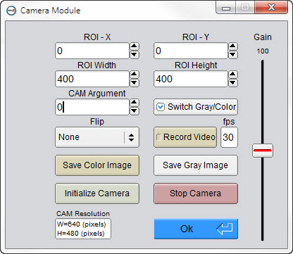
Camera Module
In order to capture the real-time projected fringe patterns, camera must be initialized from this module. Two modes (Gray and Color) are defined for the video display.
Gray mode is created for specifically realtime 3D scanning. This mode requires the dimensions of the captured screen, offset in x, y, and camera argument number (It can be 0,1,2,3,... etc. based on how many devices attached to the computer). At any time images can be saved by pressing the Save button.
Color mode is defined for display the full resolution of the camera. Both modes can be switched at any time by pressing the switch button.
Videos (Gray or Color) can be recorded at any desired frame rate. This feature is in demo stage because of OpenCV issue. In fact, OpenCV developers are working hard to fix this issue.
Flip feature is also introduced for making upside down and left side right. Well sometime we need this feature. So, I just created it.
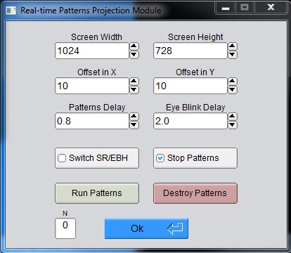
Realtime Phase Shifting of Fringe Patterns
3, 4, or 5-step fringe patterns can be projected and run as a slide show using this module. Time delay can be switched between the Steady Rate or Eye Blink Hold. Patterns can be stopped at any time during the slideshow. Once patterns are stopped, the real-time 3D scanning will also be stopped. It can start again by uncheck the stop button. During slide show, the number of the current image can be seen from the small box named “N”, where N is the number of the current fringe pattern that was just projected and captured.